In structural geology, the analysis of rock deformation in the field or at the microscope (strain analysis) allows us making some assumptions on what kind of stresses had caused those deformations (stress analysis).
Tridimensional stress components
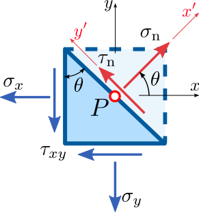
While analyzing stress, it is convenient to describe it within a coordinate system. A 2-dimensional stress has components that are parallel to the x and y axes, that is σx e σy. The corresponding shear stress will have a component τxy (linked to σx and parallel to the y axis) and a component τyx (linked to σy and parallel to the x axis). These are the 4 components of the plane stress (a particular case in which no stress is acting along the z direction, perpendicularly to the xy plane).
Stress components on an inclined plane
The stress upon a plane oriented by an angle θ with respect to the y axis is represented as in the picture at right. At a certain value of the θ angle, σ will reach its maximum value.
Principal stresses
Around 360° there are 2 directions, perpendicular to each other, at which we’ll have a maximum and a minimum value for the shear stress; stresses perpendicular to those surfaces are called the principal stresses σ1 and σ2. In these two directions shear stresses are zero.
In three-dimensional stress, the homogeneous stress can always be analyzed in terms of 3 principal stresses perpendicular to each other σ1 ≥ σ2 ≥ σ3, called main, intermediate, and minor principal stress, respectively.
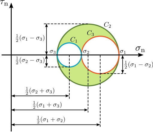
Calculating the stress on a surface whose normal is at a angle θ from the principal main stress σ1 can be performed on a diagram where σ is the x axis and τ the y axis. All the σ – τ pairs resulting on the different planes while varying the angle θ from 0 to 360° are lying on the so called Mohr’s circle.
Mohr’s Circles
The circle intersects the x axis at the values σ1 and σ3; its radius is (σ1 – σ3)/2; its center is at (σ1 + σ3)/2 and corresponds to σ2.
Maximum and minimum values of the shear stress are always on two planes at the same angle (θ ± 45°) from the main principal stress.
Higher values of shear stress are due to stress differences, not to absolute values of the principal stress. In 3 dimensions, this occurs on two conjugate surfaces which intersect along the intermediate stress axis σ2 at angles of ± 45° from σ1 and σ3.

The 9 components of the stress tensor
In different situations from the plane stress, we will have stress components along the z axis. In total, they are the 9 components of the stress tensor, 3 of which are normal to the Cartesian planes: σxx, σyy and σzz.
On planes where the shear stress is zero (τ = 0) they become the principal stress planes σ1, σ2 and σ3.

The 3 principal stresses
Stress and strain are “second-order tensors”. A scalar is a zero-order tensor (one value, no directional properties); a vector is a first-order tensor (value and direction). Second-order tensors define the interactions between vectors and directional operators.
There are 3 perpendicular planes upon which no shear stress acts upon. The same goes for deformation, where we talk about principal strain axes.