Earthquakes occur at plate margins: ocean trenchers (subduction zones), ocean and continental rifts, and transform faults.
Seismicity at ocean rifts does not exceed 10 km of depth; at transform margins it reaches down to 20 km; the biggest earthquakes occur at subduction zones, where they can be as deep as 700 km.
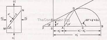
Rupture angle in a Mohr’s circle diagram
Rupture (fault formation) occurs along conjugate planes at an angle α = 45°+Φ/2 from the direction of σ1 (segment AD in the picture at left); it is there, at the y coordinate of point D, that the shear stress reaches its maximum value:
τ = C + σn tg Φ
(Coulomb’s law – the equation of the straight line tangent to the circle in the picture; the straight line is the rupture envelope), where C is the rock’s cohesion (the intersection of the rupture envelope with the y axis) and Φ is the internal friction angle (the angle between the rupture envelope and the x axis).
Another way to express the formula for the shear stress along a moving fault plane is
τ = C + (σn – P)tg Φ
simplified as:
τ = μ(σn – P)
where tg Φ = μ. P is the pore pressure, that is the pressure exerted by interstitial fluids (typically water and/or oil and/or gas). This formula is useful to understand how fluids exerting pressure against the rock’s grains will decrease the value of τ, which is the value of the shear stress needed to make a fault slip, therefore stabilizing it. It must be underlined that seismic events may occur only where the volumes of fluids extracted or injected are really enormous. Rarely, in some of the areas where fluids re-injection is carried out, some earthquakes occurred exactly because P had been increased. But this has happened only in close proximity to the fault and for enormous amounts of injected fluids, so that P increased well above the value before the extractions.
Along fault planes there are both shear and compression resistances, so both compression (P) and shear (S) waves will propagate from the hypocenter.
The wave velocities depend on the elastic moduli and on the rock’s density.
For the two main types of seismic waves (compression α and shear β) we have:
 where λ is Lamé’s first constant, μ is the second (the rigidity or Bulk modulus), and δ is the density. It is interesting to note that, even if density is the denominator and it increases with depth, the velocity of seismic waves also increases with depth; this happens because the elastic moduli, too, increase with depth, and at a higher rate than density. Therefore, it is not the body’s density that increases the velocity of seismic waves, but its elastic moduli that increase with density.
It is clear we will always have α > β, the former having a bigger numerator. The faster P waves will always arrive earlier (P = Primary) at a measuring station and on the relevant seismograph; the S waves will always come second (Secondary waves).
Charles Richter noted that the logarithm of the maximum earth displacement decreased with distance along parallel curves (diagram at right). He calculated the entity of the seismic events by comparing them to a reference event causing a maximum amplitude A0 (for S waves at first) of 0,001 mm at a 100 km epicentral distance.
Amplitude/distance logarithmic diagram: the graphs are parallel
Richter’s magnitude was defined as log A – log A0
For example: displacement A = 0,1 mm → ML = log 0,1/0,001 = 2
The magnitude od an earthquake is directly proportional to the width of the fault segment involved in the slip.
The seismic moment is defined as M0 = μSD, where μ is the Bulk modulus, S is the fault’s surface area, and D the average displacement along it.